|
Aerial Asset |
The available VBS3Strike Aircraft platforms to be assigned for the mission |
|
Observer |
Select an Observer to observe the Strike mission |
|
Msn Type |
There are four types of Missions, which are ‘9Line’,’ ABBR 9 Line’, ‘Keyhole’, ‘Polar’
- ‘9Line’ is the normal mission type activated
with all required features
- ‘ABBR 9 Line’ deactivates the ‘IP/ BP’, ‘Heading’ and ‘Distance’ values. This mission type will consider the aircrafts current position as the Initial IP. Therefore if the distance between current &and target positions is insufficient to create a mission then “Target not in range for the selected weapon” message will be displayed.
- Keyhole uses letters for direction and distance
in nautical miles. A = North, B= East, C= South, D = West.
For example, D2, the start location or “Initial Point” would be located
two nautical miles to the west from the reference point.
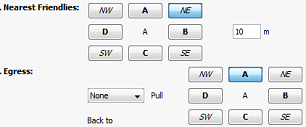
∆ Image 3d.1: When a Keyhole mission is entered, the egress button array changes according to keyhole letters |
- Polar is similar to Key hole but uses degrees
for direction
Note:
When using Keyhole or Polar, Heading and Distance attributes are ignored
For both Polar and Key hole missions, a validation error message will be displayed if an invalid refinement value is given.
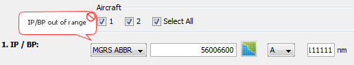
∆ Image 3d.2 Error message |
- 5line missions
This feature supports for both Fixed Wing and Rotary wing assets and allows to use all attack profiles available for those assets. When the 5line mission type is selected from Observer IP and Warning Order panel, the 5line panel is displayed on the Instructor Control Panel. IP/BP selection is diactivated for 5line mission type.
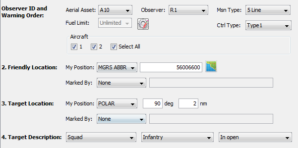
∆ Image 3d.3: 5line mission panel |
Safety zone for Friendly location falls between 10 degrees left and 10 degrees right from the line which can be drawn between target and friendly location.
The IP will be calculated internally, and it can be fallen in two regions.
Those are basically from the side of left shoulder from the friendly units and right shoulder from the friendly units. Those two regions are 90 degrees each according to the image 3d.4.
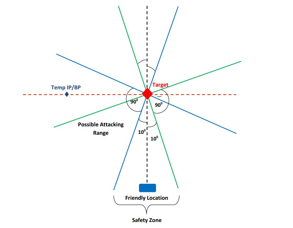
∆
Image 3d.4: Selecting valid Initial Point |
Always the line which can be drawn between target to IP should fall inside those two regions.
Determining Target location using Polar grid type:
If the target location is selected as Polar, the exact target location will be determined relatively to the friendly position.
If polar grid type is used for determining the Friendly location, the adjusted location will be considered. Based on this, when Polar type is used for the target location, it will use the adjusted friendly location value to calculate the target location.
Example:
When selecting the friendly position using the Polar type, given values
59606350 for the Friendly location, 90 deg and 1nm, when executing the mission, it will consider the adjusted friendly position. Then the target will be calculated as a position which is located in 90 deg direction and 2nm distance from the new Friendly location.
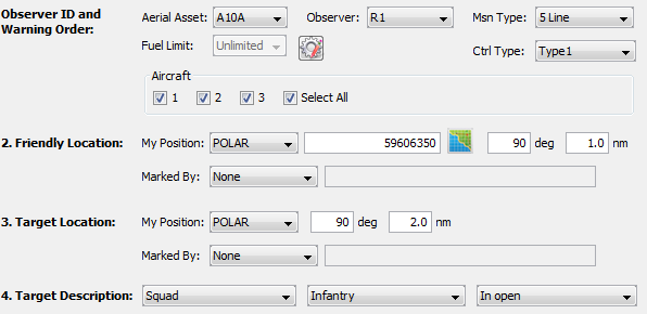
∆
Image 3d.5: Polar value for Friendly location |
|
Ctrl Type |
When a Strike mission is underway, the control type has to be specified. This does not affect the simulation, but it will be used for realistic training. Available control types are:
This information will be recorded in mission details for each and every task so that the user can go through each task and see with which control type category a particular task has been created. |
|
Fuel Limit |
Limited: The Instructor can define how much fuel time an aircraft needs to reach the ‘First release point’ until refuel is needed. The time allocated cannot be empty or else the error message “Time should not be empty” will be shown as in Image 3d.6 The time allocated should be sufficient for the aircraft to fly to the ‘First Release point’ or else the error message “Insufficient Fuel Limit” as in Image 3d.7 will be displayed.
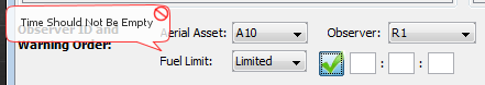
∆
Image 3d.6: Invalid Fuel Limit |
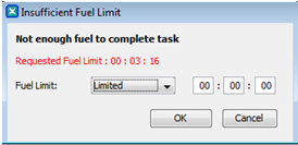
∆
Image 3d.7: Insufficient Fuel Limit |
|
Aircraft |
Select the air platform to be assigned for the mission |
Initial Point/ Battle Position |
The starting grid location for the mission. The following reference grid types are available: MGRS ABBR, MGRS, UTM and REF PT.
MGRS ABBR This is an eight digit reference value. This value can be retrieved by zooming the VBS3 2D Map (only if the coordinate system type is set to MGRS in VBS3 scenario settings) where it displays the horizontal (x axis) four digits and the vertical (y axis) four digits and combining them. (For instance if the x axis value ’5600’ and y axis value is ‘6600’ then the final grid value is ‘56006600’)
MGRS ‘From Map’ button: when this button is clicked, then VBS3 will switch to RTE mode. Once a grid point is selected, that grid will be generated into the VBS3Strike application.
Note:
In IP/ BP, ‘East/ West’, ‘North/ South’ and ‘Hold at Height’ variables are active only when Rotary wing selected.
UTM -> UTM coordinates of a position is a 14 digit value. This can be obtained from VBS3 2D map by following either of the methods below.
Method 1 :
Select and right click any object such as a unit or a marker and select the ‘GPS Positioning’ option. This will open up ‘GPS Coordinate Settings’ window. The current section will displays the MGRS & UTM coordinates of that object.
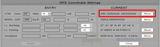
∆
Image 3d.8: GPS Coordinate Settings |
Method 2 :
In VBS3 2D Map go to Tools -> Scenario Settings and select Coord Sys Type as “UTM”
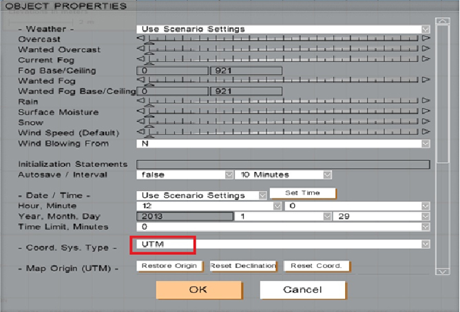
∆
Image 3d.9: GPS Object Properties |
In the VBS3 2D Map view, select the exact target location by zoom In/Zoom out. The GPS Positioning Value will be displayed in the bottom of the map, as shown below.
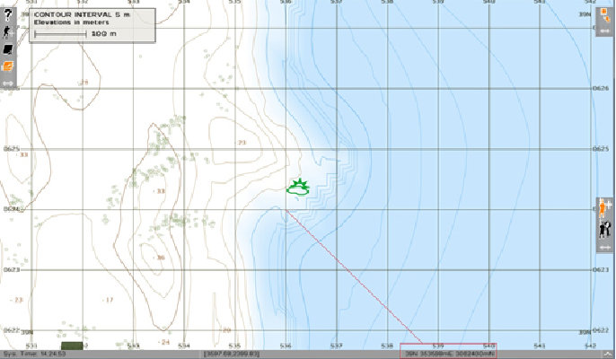
∆
Image 3d.10: GPS Positioning Value |
If there is a missing coordinate value, add a 0 in front to replace the missing Grid value. Eg: 0359600 3063500
Note:
Grid locations are validated so that the grid values which are outside the map and the margin values cannot be used.
|
Heading |
The flying direction of the aircraft while on attack |
Distance |
Distance to target. |
Target Elevation |
The height to the target |
Target Description |
The Size, Type and Status of the target can be given as information to be viewed. |
Target Location |
The target grid location needs to be specified. The following reference grid types are available: MGRS ABBR, MGRS, UTM and REF PT.
‘From Map’ button: when this button is clicked, then VBS3 will switch to RTE mode. Once a grid point is selected, that grid will be generated into the VBS3Strike application. Note:
‘From Map’ button cannot be utilized when the POD/HUD view is active.
‘Same as Ref. Point’ checkbox: Select this option if the ‘Target Location’ is same as the ‘Reference Point’.
Select Key Hole / Polar as the Start Location Refinement, only then will the Target Location “Same as Reference Point” check box be enabled.
|
Mark Type |
This specifies the ability to provide a ‘Smoke’ round, ‘ILLUM’ round, ‘Designator’ or ‘IR’ to appear at the vicinity of the target prior to the weapon release.
Magic Mark contains five values:
- None - do nothing
- Smoke
- white phosphorus shell
- ILLUM - ILLUM is mostly used at night time and
therefore it used to make some light effect near the target. This lets
the Friendly units identify the target at night. Illum round will
explode 45 seconds prior to the explosion
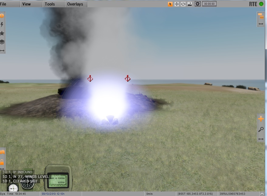
∆
Image 3d.11: ILLUM Effect |
- Designator with PRF (Pulse Repetition Frequency) code support
A laser designator is a laser light source which is used to designate a target. Laser designators provide targeting for laser guided bombs, missiles, or precision artillery munitions.
VBS3Strike is able to detect the designation of any player joined to the scenario as trainees. While the Trainee designates the target VBS3Strike will pick the closest laser to a desired reference point .Normally this should be the target location. VBS3Strike will detect any laser designation within radius of 800m from the initially given target.
∆ Image 3d.12: lasing scenario |
When the user selects Designator as the Mark Type at the task creation, a text box appears to enter the PRF code.

∆ Image 3d.13: Adding PRF code to the laser designator |
Note:
Valid PRF code must be in range of ‘1111-1788’ and only 1-8 digits can be used. If the user does not enter a PRF code, ‘1111’ is set as the default PRF code. This PRF code is common to all the aircrafts going for the attack and it will be displayed in HUD/POD/Manual Control/Pilot mode/Instructor POD views.
When the projectile is released, the relevant PRF code along with the projectile will be displayed in Strike Projectile Analysis window. If the released weapon is not associated with a laser guided weapon, the PRF column will display ‘N/A’

∆ Image 3d.14: Strike Projectile Analysis window |
Setting PRF to laser designator equipment
- In VBS3 player, switch to laser designator item
- Scroll to get the functions of the laser designator
- Select ‘Set PRF Code’
- Clear the default PRF in the panel and enter a valid PRF code
- Click Enter to set the PRF
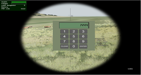
∆ Image 3d.15: Setting PRF code to the laser designator equipment |
Weapons will be fired to the place which the observer is pointing the laser with the same PRF code given at the task creation. Initial target will be hit if same PRF code laser is not found in the particular area.
Note:
In a scenario where multiple laser designators with the same PRF code are used, then the laser target which is closest to the initial target will be considered.
Must know facts
- projectiles has an error of not achieving the
target (e.g. for lbs bomb with a velocity of 35m/s has an error rate
of 35cm)
- projectile guidance is activated when the
target is 3km or less. ( the further away the more time the projectile
has to turn towards the target. thus allowing an accurate hit)
- the projectile doesn't make high angle turns.
it gradually turns (to make it somewhat realistic)
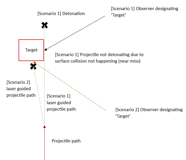
- the angle between the direction vector from the projectile position to the lased location and the current direction of the projectile must be less than or equal to 30° degrees. else the projectile will hit old target.
If you have a look at the above illustration, it shows two scenarios.
Scenario 1
Observer designates to the side of the target and the projectile doesn't detonate even if the target is achieved. The projectile is not firing a collision event with the surface area. (near miss)
Scenario 2
Observer designates in such a way (with projectile release direction in consideration) so that the projectile shall definitely detonate. The projectile has sufficient surface area to accept as a collision event
If scenario 1 happens the projectile shall travel until it hits a surface. throughout that period of miss the TTT (count down) shall be 0
Note:
The laser designating point can vary within 15 degrees to the given target.
Below mentioned Laser Guided munitions should be used as weaponry types.
Laser Guided Bombs |
2000lb_bomb_guided_GBU10 |
1000lb_bomb_guided_GBU16 |
500lb_bomb_guided_GBU12 |
250lb_bomb_guided_GBU39 |
Laser Guided Missiles |
AGM65E (Maverick) |
AGM114K_missile |
AGM114M_missile |
AGM114N_missile |
AGM114P_missile |
Note:
If the particular aircraft can’t find any valid laser designation at the release point then weapons won’t fire and it displays the aircraft status as “Unable to Engage: No Laser detected” message on VBS Transmissions panel and VBS side chat though the user has used Laser Guided munitions.
- IR – IR uses Infrared Zoom Laser Illuminator Designator (IZLID)
|
Nearest Friendlies |
Details of the Friendlies near the target in a particular direction and distance is given here. |
Egress |
If ‘Left’ or ‘Right’ selected as the Egress direction, then the aircraft may turn to that direction after the last weapon is fired. But if ‘None’ is selected then the aircraft will turn to the optimal direction in order to get the user specified egress direction and then fly around 2km (2000m) along that direction in a straight path. |
